Ground Penetrating Radar
Ground-penetrating radar (GPR) is a geophysical method that Ground Penetrating Radar (GPR) uses a high frequency radio signal that is transmitted into the ground and reflected signals are returned to the receiver and stored on digital media. The computer measures the time taken for a pulse to travel to and from the target which indicates its depth and location. The reflected signals are interpreted by the system and displayed on the unit's LCD panel.
GPR uses high-frequency (usually polarized) radio waves, usually in the range 10 MHz to 1 GHz. A GPR transmitter emits electromagnetic energy into the ground. When the energy encounters a buried object or a boundary between materials having different dielectric constants, it may be reflected or refracted or scattered back to the surface. A receiving antenna can then record the variations in the return signal. The principles involved are similar to seismology, except that electromagnetic energy is used instead of acoustic energy, and energy may be reflected at boundaries where subsurface electrical properties change rather than subsurface mechanical properties as is the case with seismic energy.
Ground-penetrating radar antennas are generally in contact with the ground for the strongest signal strength; however, GPR air-launched antennas can be used above the ground.
How does GPR work ?
GPR Data Collection (below ground)
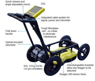
In order to find the location and depth of an object, buried subsurface, various types of GPR equipment are used to collect the data. The type of GPR equipment required is dependent on the depth and size of the target to be located. The radar unit emits and receives reflected signals up to a thousand times per second. These signals are viewed by the field operator on location immediate analysis and are also stored in the system and downloaded to a computer for further data analysis if required.
GPR Data Collection (in concrete)
To locate objects such as rebar, conduits and post-tension cables embedded in concrete, a high frequency GPR system is used. The data can be collected in simple line scans to determine the thickness of concrete or in a grid format which will produce a map of any targets located in the concrete. Using this method we can look at virtual slices in the image to determine the depth of the objects and create a 3D map of the image.
GPR Data Analysis
GPR waves travel through many different materials. Different types of soil, concrete, fill material, debris, and varying amounts of water saturation all have different dielectric and conductive properties that affect the GPR waves, and thus GPR data interpretation. Although the data images are displayed on the screen they still require someone with field experience to interpret them in order to accurately determine the findings.
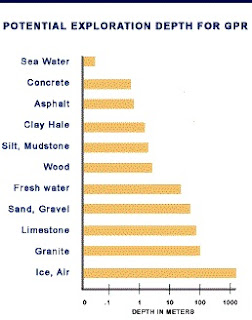
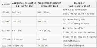
This is probably one of the most commonly asked questions. In most cases an estimated depth range can be determined with accuracy based upon the subsurface material and the frequency of the GPR antenna. For applications requiring higher resolution, such as locating rebar or conduits in concrete, a higher frequency GPR system (1,000 MHz) is used. This will give high resolution detail for down to approximately 24 inches in depth. Applications which require deeper penetration in ground soil requires a lower frequency (12.5 MHz to 500 MHz). Depending on the subsurface material the depth range can be from a few inches to thousands of feet (as indicated in the chart).
Applications
GPR has many applications in a number of fields.
1. In the Earth sciences it is used to study bedrock, soils, groundwater, and ice. It is of some utility in prospecting for gold nuggets and for diamonds in alluvial gravel beds, by finding natural traps in buried stream beds that have the potential for accumulating heavier particles. The Chinese lunar rover Yutu has a GPR on its underside to investigate the soil and crust of the Moon.
2. Engineering applications include nondestructive testing (NDT) of structures and pavements, locating buried structures and utility lines, and studying soils and bedrock.
3. In environmental remediation, GPR is used to define landfills, contaminant plumes, and other remediation sites,
4. In archaeology it is used for mapping archaeological features and cemeteries.
5. GPR is used in law enforcement for locating clandestine graves and buried evidence.
6. Military uses include detection of mines, unexploded ordnance, and tunnels.
Limitations
The most significant performance limitation of GPR is in high-conductivity materials such as clay soils and soils that are salt contaminated. Performance is also limited by signal scattering in heterogeneous conditions (e.g. rocky soils).
Other disadvantages of currently available GPR systems include:
- Interpretation of radargrams is generally non-intuitive to the novice.
- Considerable expertise is necessary to effectively design, conduct, and interpret GPR surveys.
- Relatively high energy consumption can be problematic for extensive field surveys.
Radar is sensitive to changes in material composition, detecting changes requires movement. When looking through stationary items using surface-penetrating or ground-penetrating radar, the equipment needs to be moved in order for the radar to examine the specified area by looking for differences in material composition. While it can identify items such as pipes, voids, and soil, it cannot identify the specific materials, such as gold and precious gems. It can, however, be useful in providing subsurface mapping of potential gem-bearing pockets, or "vugs." The readings can be confused by moisture in the ground, and they can't separate gem-bearing pockets from the non-gem-bearing ones.
When determining depth capabilities, the frequency range of the antenna dictates the size of the antenna and the depth capability. The grid spacing which is scanned is based on the size of the targets that need to be identified and the results required. Typical grid spacings can be 1 meter, 3 ft, 5 ft, 10 ft, 20 ft for ground surveys and 1 inch to 1 feet for walls and floors.
The speed at which a radar signal travels is dependent upon the composition of the material being penetrated. The depth to a target is determined based on the amount of time it takes for the radar signal to reflect back to the unit’s antenna. Radar signals travel at different velocities through different types of materials. It is possible to use the depth to a known object to determine a specific velocity and then calibrate the depth calculations.


0 comments:
Post a Comment