A short introduction to plane tabling- A graphical method of Surveying.
Plane Table Survey:
Plane Table Survey is a method of Surveying in which field work and the office work are done simultaneously. It is also known as the graphical method of Surveying. A manuscript map is made in the field and the topographic details can be filled in later.
 |
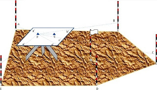
| Plane-Table Cut-a-way, shows a part of the table and the tripod stand |
List of Instruments used in Surveying:
(1) Plane Table
(3) Plumbing fork and Plumb bob
(4) Spirit Level
(5) Chain or Tape
(6) Rain roof cover for the plane table
(7) Compass
(8) Ranging Rods
(9) Drawing Sheets
(10) Drawing equipment.
Procedure:
To do the plane tabling one has to follow the following procedure at every plane table set-up:
(a) Fixing the plane table to the tripod stand
(b)Setting up and temporary adjustments:
- Leveling the plane table with the help of spirit level
- Centering with the help of plumbing fork
- Orientation by trough compass or by back sighting
(c) Sighting the points with the help of Alidade
Methods of plane tabling:
1. For locating details:
(a) Radiation Method: A ray is drawn towards the point with the help of the Alidade. With the help of Chain or Tape the horizontal distance is measured from the Plane Table to the point and this point is located on the sheet by plotting it into the scale of the map.
Procedure:
- Select a suitable point P on the ground such that all the details are visible from it
- Center and level the plane table over P
- Mark the direction of the North on the sheet by using compass
- Locate instrument station p on the sheet by using plumbing fork, such that p on sheet is exactly over P on ground
- Centering the alidade on point p sight various details step by step and draw a ray from each detail along the fiducial edge of the alidade
- Let the details be named as A, B, C, D, E etc.
- Now measure the distances of each point from P i.e. PA, PB, PC, PD, PE and plot them to scale on the sheet as pa, pb, pc, pd, pe respectively
- Joint a, b, c, d, and e to give the outline of the details

NOTE: These details may be building corners, electric towers, tree, manhole etc. But for demonstration purpose we will put ranging rods.
Significance and Applications
This is the easiest method in plane tabling. It is used when:
- All the details are visible and accessible from one instrument station
- The ground is level and smooth
- Distances are so small that can be measured with single tape
(b) Intersection Method: In this method two instrument stations are used but no chain or tape is required. Intersecting rays are drawn from these two stations whose location is already plotted (by measuring the distance between them), the point of intersection is the location of the point.
Procedure:
 |
| Figure 2 |
- Select two instrument stations P and Q, such that all the points or details to be located are visible from both the stations.
- Now set the table on P and make it centered and level.
- Using the plumbing form locate the ground station on the sheet i.e. p, such that the point p on the sheet is exactly over the point P on the ground.
- Measure the distance between P and Q.
- Now using the alidade pivoted at P orient the table so that other instrument station Q is sighted and clamp the table and draw a line along the fidicual edge of the alidade according to a suitable scale. This line pq is a base line and hence must be measured and drawn accurately
- With the alidade pivoted on p sight other details and draw rays as a’, b’ c’, d’ etc as shown in Figure 1.
- Now shift the table to station Q and make it centered and leveled such that point q on sheet is exactly above the Q on the ground
- With the alidade placed along line pq orient the table and back sight the station P and clamp the table.

Figure 3 - With the alidade pivoted on q sight other details and draw rays as a’’, b’’ c’’, d’’ etc as shown in Figure 2.
- The intersection of a’, b’ c’, d’, e’ with a’’, b’’ c’’, d’’, e’’ are named as a, b, c, d, e respectively. Join a, b, c, d, e as shown in Figure 3.
NOTE: These details may be building corners, electric towers, tree, manhole etc. But for demonstration purpose we will put ranging rods.
Significance and Applications
In this method a base line is drawn between two instrument stations. The significance of this method is that only the base line is measured and ploted to scale very accurately. Other points or details depends on the scale and accuracy of the base line. It is used when:
- The ground is not level and smooth
- Distances are so large that cannot be measured with single tape
2. For locating Plane Table Stations:
(a) Traversing: This method of plane table surveying is used to plot a traverse in cases stations have not been previously plotted by some other methods. In this method, traverse stations are first selected. The stations are plotted by method of radiation by taking back sight on the preceding station and a fore sight to the following station. Here distances are generally measured by tachometric method and surveying work has to be performed with great care.
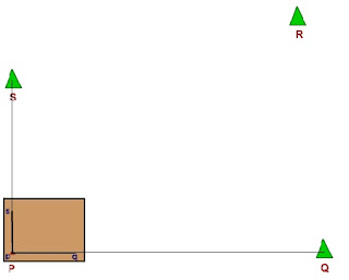
Let us consider the stations P, Q, R and S which are to plotted by method of traversing. Stations are to be chosen in such a way that adjoining stations are visible. First, the plane table is to be set at station P and then plotted as p. The orientation of the table and scale of plotting should be such that all other stations will be accommodated within the boundary of the sheet. With the alidade pivoted at p, draw the rays to Q and S. Distances PQ and PS are measured and plotted on the respective rays, pq and ps respectively.
The plane table is then shifted to station Q, get it set and then oriented by back sighting to station P. With the alidade pivoted at q, draw a ray to R. Distance QR is measured and plotted on the ray as qr. In this way, plane table is shifted to stations R and S and corresponding rays are drawn to obtain the plotting of the traverse pqrs.
Check lines. To check the accuracy of the plane table traverse, a few check lines are taken by sighting back to some preceding station. In this example, a check line rp is drawn from the station R to P when the plane table is occupying the station R. If the traverse is correct, the check line rp would pass through p, the plotted position of station P.
Likewise, a check line sq is drawn from S to Q. In case there is no suitable preceding station visible, any well-defined point, such as a corner of a building or a tree, which has been previously plotted, can be used for checking.
Error of closure : If the traverse to be plotted is a closed traverse, the foresight from the terminating station should pass through the first station. Otherwise the amount by which plotted position of the first station on the foresight fails to close is designated as the error of closure. It is adjusted graphically, if the error is within permissible limits, before any further plotting works are done.
(b) Resection: (See the video www.youtube.com)
In this method, the location of the station occupied by the plane table, is obtained by means of drawing rays from the stations whose locations have already been plotted on the paper. Resection may be done with the help of two points or three points.
Procedure :
- Select a base line PQ on ground, measure it accurately with steel tape.
- Setup table at P, Center it,Placing alidade at line pq.
- Orient table by running ray until Q sighted, clamped it.
- With alidade touching p, sight R, which is to be located by Resection.
- Shift the instrument and setup at R, orient the table by taking back sight on P, clamp it.
- With alidade centered at q, sight the station Q and draw a ray.
- The point of intersection of this ray and that previously drawn from p gives the required point r.

This method is called Back Ray method.
The others cases of Resection are:
1) Two Point Problem
Two point problem consist in locating the position on the plan of the station occupied by the plane table, by means of observation to Two well defined points, which are visible from the instrument station and whose position have been already plotted on the plan.
2) Three Point Problem
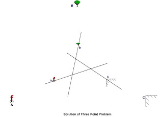
 In this method, three well defined points, having locations already being plotted on the drawing are involved. These are used to find and subsequently plot the location of the plane table station.
The method is based on the fact that, in a correctly oriented plane table, resectors through well defined points get intersected at a point which represents the location of the plane table station on the drawing. For example, as shown in Figure, if X, Y and Z are well defined objects present in the field whose plotted positions are x, y and z. Now, if the plane table is oriented correctly, the three resectors Xx, Yy and Zz get intersected at p which represents the location of the plane table station, P on the drawing sheet. Thus, through solution of three-point problem, both orientation and resection of plane table gets accomplished simultaneously.
There are several methods for solution of the three point problem: (i) trial and Error method, (ii) mechanical method, (iii) graphical method, (iv)Analytical method and (v) geometrical construction method. Of these, the trial and error method is easy, quick and accurate. It is commonly used in practice and hence, has been discussed in detail.
Trial and Error method of Solution of Three Point Problem
In three point problem, if the orientation of the plane table is not proper, the intersection of the resectors through the three points will not meet at a point but will form a triangle, known as triangle of error. The size of the triangle of error depends upon the amount of angular error in the orientation.
 The trial and error method of three point problem, also known as Lehman's method minimises the triangle of error to a point iteratively. The iterative operation consist of drawing of resectors from known points through their plotted position and the adjustment of orientation of the plane table.
The estimation of location of the plane table depends on its position relative to the well defined points considered for this purpose. Depending on their relative positions, three cases may arise :
(i) The position of plane table is inside the great triangle;
(ii) The position of plane table is outside the great triangle;
(iii) The position of plane table lies on or near the circumference of the great circle.
In case of (iii), the solution of the three-point problem becomes indeterminate or unstable. But for the cases (i) and (ii), Lehmann's rules are used to estimate the location of plane table.
Lehmann's rules
1. If the position of plane table station is inside the great triangle, its plotted position should be chosen inside the triangle of error.
2. If the position of plane table station is outside the great triangle, its plotted position should be chosen outside the triangle of error.
3. The plotted position of the plane table should be so chosen that its distance from the the resectors is proportional to the distance of plane table station from the field positions of the considered objects.
4. The plotted position of the plane table should be so chosen that it is to the same side of all the three rays.
4(a). If the position of plane table station is outside the great circle, its plotted position should be so chosen that
- It lies on the same side of ray to the most distant point as the intersection k of the other two rays.
- The intersection of two rays to the nearer points, is midway between the plotted position of the station and the ray to the most distant point.
4(b). If the position of plane table station is outside the great triangle but inside the great circle, the plotted position of the station is so chosen that the ray to the middle point lies between plotted station position and the intersection of the rays to the two extreme points.
Steps for Solution of Three-Point Problem
 Let X, Y, and Z represent the ground location of the well defined objects whose plotted positions are x, y, and z, respectively. Let P be the plane table station whose plotted position, say p, is to be determined.
(i) Select a plane table position inside the great triangle XYZ and set up the table over P and orient it by judgment so that apparent line xy is approximately parallel to the imaginary side XY.
(ii) Pivoting the alidade on x, y, and z bisect the signals placed at X, Y, and Z in turn and draw rays. If the orientation of the table is correct, the three rays will meet at one point which is the desired location of p on the sheet. If not, the rays will form a triangle of error.
(iii) Choose a point p' inside the triangle of error such that its perpendicular distances from each ray is in proportion to the respective distances of P from the three ground objects. For selection of location of p', Lehmann's rules (1) and (3) need to be applied.
(iv) Align the alidade along p' x (assuming X to be the farthest station) rotate the table till flag at X is bisected, and clamp the table.
(v) Pivoting the alidade on x, y, and z repeat the process as in step (ii) above. If the estimation of p as p' is correct, the three rays will intersect at a point otherwise again a triangle of error will be formed but of smaller size and within the previous triangle of error. .
(vi) Estimate again the location of p' in the new triangle of error applying the rules, (i) and (iii), and repeat the steps (iv) and (v).
(vii) The method is repeated till all the three rays intersect at a point. The point of intersection is the required location p of the plane-table station P.
The Points to be kept in mind while surveying with plane table:
- The small letters a,b,c are used to represent the stations on the paper.
- The table will remain stationary while the alidade is rotated to sight the station.
- While taking the reading the alidade must be centered.
- The board is turned only when the table is to be oriented.
ADVANTAGES
- It is most suitable for preparing small scale maps.
- It is most rapid.
- The field book is not necessary as plotting is done in the field concurrently with the field work, and hence the mistakes in booking the field notes are avoided
- The surveyor can compare the plotted work with the actual features of the area surveyed and thus can ascertain if it represents them properly, and cannot therefore, overlook any essential features
- There is no possibility of omitting the necessary measurements as the map is plotted in the field.
- Errors of measurement and plotting may be readily detected by check lines.
- Contours and irregular objects may be represented accurately, since the tract is in view.
- It is particularly advantageous in magnetic areas where compass survey is not reliable.
- It is less costly than a theodolite survey.
- No great skill is required to prepare a satisfactory map.
DISADVANTAGES
- The plane table is essentially a tropical instrument. It is not suitable for work in a wet climate.
- It is heavy, cumbersome, and awkward to carry.
- There are several accessories to be carried, and therefore, they are likely to be lost.
- It is not intended for accurate work.
- If the survey is to be replotted to a different scale or quantities are to be computed, It is a great inconvenience in absence of the field notes.


0 comments:
Post a Comment